Question
a.
1
b.
0
c.
x
d.
x'
Posted under Digital Logic Design
Engage with the Community - Add Your Comment
Confused About the Answer? Ask for Details Here.
Know the Explanation? Add it Here.
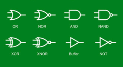
Q. Adder-subtractor operating on mode 1 at (X XOR 1) gives
Similar Questions
Discover Related MCQs
Q. Read operation in memory is performed when WE is
View solution
Q. Subtraction of two numbers can be done using
View solution
Q. 2x1 multiplexer has
View solution
Q. To start the addition carry flag is
View solution
Q. No greater than 9 in BCD creates
View solution
Q. The integrated circuits to be used in experiments can be classified as Small Scale Integration (SSI) and?
View solution
Q. 8 input mux will have
View solution
Q. Edge triggered flip-flops can be
View solution
Q. Lamp handball game uses application of bidirectional shift register
View solution
Q. 4bit parallel adder produces output of
View solution
Q. LED stands for
View solution
Q. When the mode of adder subtractor is 0 than it
View solution
Q. Memory can be expanded using two
View solution
Q. In order to provide proper current to the leds of 7 segment with Vcc we use
View solution
Q. Integrated circuit number 74194 consists of
View solution
Q. Integrated circuit number 72555 timer is same as
View solution
Q. 16x4 RAM indicates that memory location are
View solution
Q. Integrated circuit number 74195 consists of
View solution
Q. BCD counter is
View solution
Q. 4bit counter will be incremented by
View solution
Suggested Topics
Are you eager to expand your knowledge beyond Digital Logic Design? We've curated a selection of related categories that you might find intriguing.
Click on the categories below to discover a wealth of MCQs and enrich your understanding of Computer Science. Happy exploring!


